Recently, I started working on a second quadrupedal robot build. The first one turned out to be heaps of fun to design and program but ultimately failed to achieve its goal of being able to walk.
I still learned a lot from the build and have now a good idea of what I'm looking for when building the second quadruped. A major issue with the first one was the leg assembly which would bend as it was too flimsy and which could not lift the quadruped when in trod gait where two legs have to carry the entire robot. A contributing factor was also the weight of the two batteries and all the electronics that I didn't strictly needed.
With that in mind, the new version should have more rigid legs, with stronger motors and better mounting of the motors and joints. Additionally, I would like to add a custom PCB containing all the electronics I need.
What a mess! And the connectors got loose all the time.
With the second incarnation I want to improve the sturdiness of the body and the legs and I would love to incorporate encoders to track the absolute leg positions. I also want to design my own PCB to make the electronics lighter and more suitable for the task.
This time around however, the focus is on planning and researching to be able to come up with a design that works much better and that I can use to further develop the platform.
Update
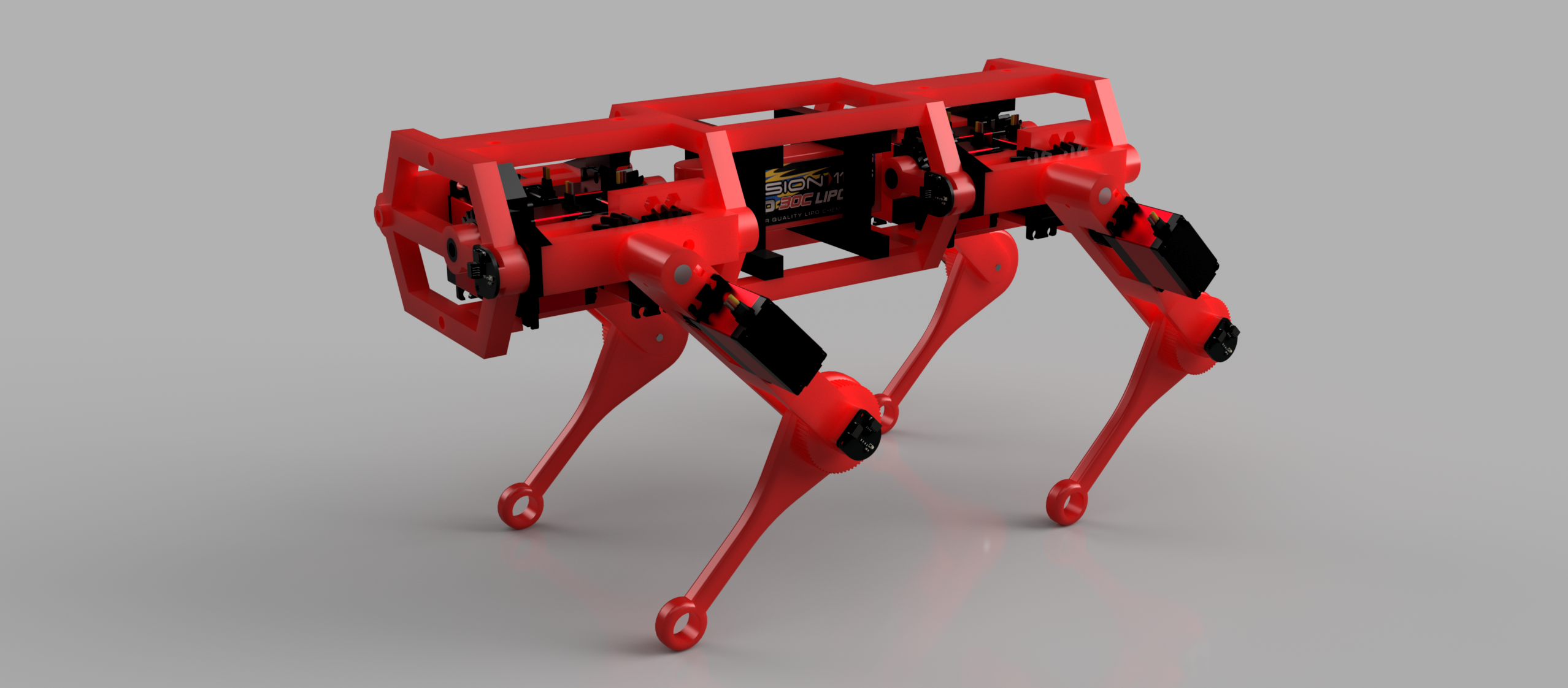
I actually got around building it and it got all the feature I wanted. It even walked and not too bad either. The current main board has an issue though preventing it from driving the servos, ultimately limiting the quadruped to just a few moves. I yet have to find some time to document my journey. I'll post some photos below in the meantime.
A render of the close to final robot.
Starting with prototyping the upper leg joint as it's the hardest to get right
I decided to use timing belts to transfer torque to the lower leg joint and needed 3D printed pulleys which turned out to work well.
The first leg assembly with the lower leg motor installed. Color choice was not final at that stage.
Second iteration of the upper leg joint with some hints of the shoulder joint. Color choice has been made.
Installing the joint into the first iteration of the body.
I wanted encoders for absolute joint position. Those were the first PCBs I ever designed holding AS5600L ICs.
Building a testing rig for a single leg assembly before I commit to building 3 more of them. This step has paid off a lot.
Testing the first complete leg with all 3 joints. It could lift something like 100g on top of its own weight, not quite enough.
The next iteration used very strong hobby servos and a 1:2 belt reduction. It was capable of carrying around 2kg
Those servos need a lot of power. So I developed a power board with an LTC3886. Really challenging board as my second PCB design.
Up next was the logic board on which the power board just mounted on. I would later create a single board to make everything even more integrated.
Starting to assemble a complete leg. There are two metal rods at the top right with the thin one being for the lower leg joint and the thicker one for the upper leg joint. That thicker aluminum rod allowed me to drill holes through it which makes torque transmission much more reliable.
Slowly assembling all the legs and mounting them to the body.
Fully assembled and turned on for the first time.
Working on some improvement for the cable management.
Much better that way. Compare that with the first quadruped from above.
An evolution of main boards. I learned so much building these.