How to setup custom ESP32-S2 boards in PlatformIO

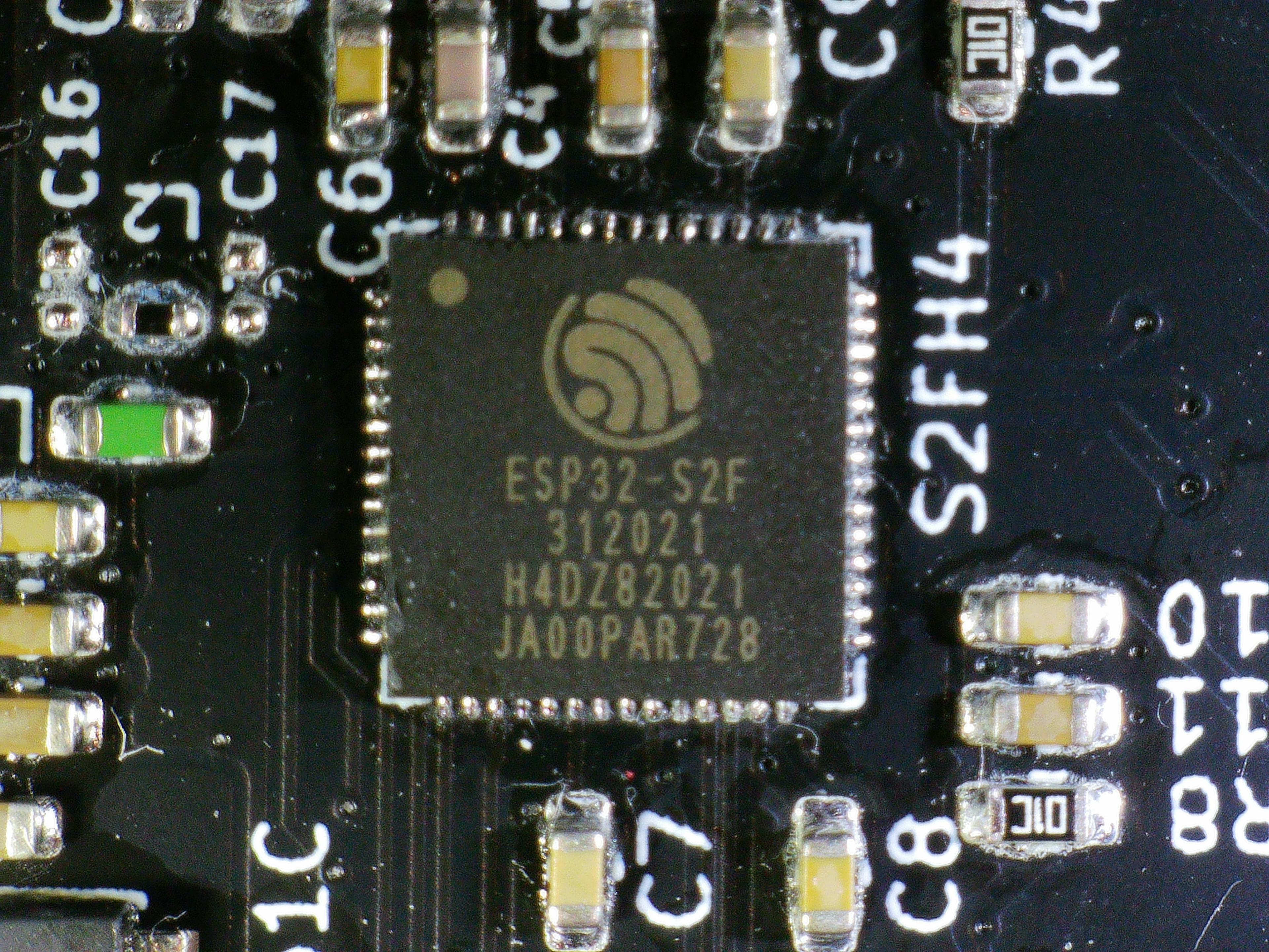
A couple month back, I built a new board with an ESP32-S2 for a little project of mine. In the past, I have used the ESP32 PICO D4 which is probably one of the easiest ICs in the ESP32 lineup when it comes to board design as it has heaps of components like the crystal already build into the die. The one thing the PICO D4 does not have, though, is native USB support and that's what makes the S2 and S3 special compared to other ESPs. Using an S2 means the PCB doesn't need a dedicated USB to UART IC like the CP2102n which reduces cost and simplifies the board.
One challenge of building custom boards with new ESPs is the board setup in PlatformIO (sorry, no Arduino IDE). I ultimately was successful but it took a bit of trial and error to get there. What follows is an attempt to summarize what I've learned.
If you're just after a the setup guide, just jump straight to A better setup.
Initial setup
In PlatformIO, we have three places to influence how building for, and interacting with a board will work.
platform.ini, each and every PlatformIO project has one and it can contain all sorts of configurations. Library dependencies are amongst the most common configurations found in this file.- The board config in
boards/$board_name.jsoncontaining configurations dedicated to a particular board, and lastly - Variant files under
variants/$board_name/
I usually design parts that I have less experience with using existing boards. In this case, I used a small board named QT Py S2 from Adafruit. Go check it out and maybe get one for yourself, Adafruit makes awesome boards and contributes much to the open hardware community.
If I would use Adafruit's board directly, all I would need to do is to set the correct board name in platform.ini like so:
[env]
board = adafruit_qtpy_esp32s2
This will implicitly load
- the board config from
boards/adafruit_qtpy_esp32s2.json, and
- the variant files from
variants/adafruit_qtpy_esp32s2/
But since I'm building a custom board, I have to at least add the files to my project. By mostly copying files from the QT Py S2 board, I ended up with the following structure assuming neon to be my board name.
$project_root/
├── boards/
│   └── neon.json
├── src/
│   └── main.cpp
├── variants/
│   └── neon/
│       ├── bootloader-tinyuf2.bin
│       ├── partitions-4MB-tinyuf2.csv
│       ├── pins_arduino.h
│       ├── tinyuf2.bin
│       └── variant.cpp
└── platform.ini
The only thing I had to change in neon.json was the name of the board and the manufacturer. Strangely, I also had to change build.arduino.partitions from partitions-4MB-tinyuf2.csv to variants/neon/partitions-4MB-tinyuf2.csv. That should have given me pause but I didn't care. Everything was working.
UF2
After some time, two things made me wonder: the fact that the variants directory contains a lot of files ending in tinyuf2 and the below warning message.
Warning! The `$PROJECT_DIR\variants\neon\tinyuf2.bin` UF2 bootloader image doesn't existI went digging and read UF2 Bootloader Details and One chip to flash them all. Both of those articles tell us that we expect to see a Mass Storage Class (MSC) device like a USB stick when plugging the board into the computer's USB port. That's not the behavior I got. Maybe the warning from above holds the clue. 🤨
After searching for the string, I found the code responsible for flashing the ESP in the Arduino ESP32 framework repo . It turns out that variables like
$PROJECT_DIR and $BUILD_DIR where not substituted when checking for file existence. After fixing this locally (and putting up a PR ), I finally got the advertised behavior.

Now, how to use this? We can use Adafruit's tooling to generate a UF2 formatted image from our
firmware.bin which we find in .pio/build/$board_name/ after building our project.
pio run # or use the "PlatformIO: Build" action
cd .pio/build/neon/
uf2conv.py firmware.bin -c -b 0x00 -f ESP32S2
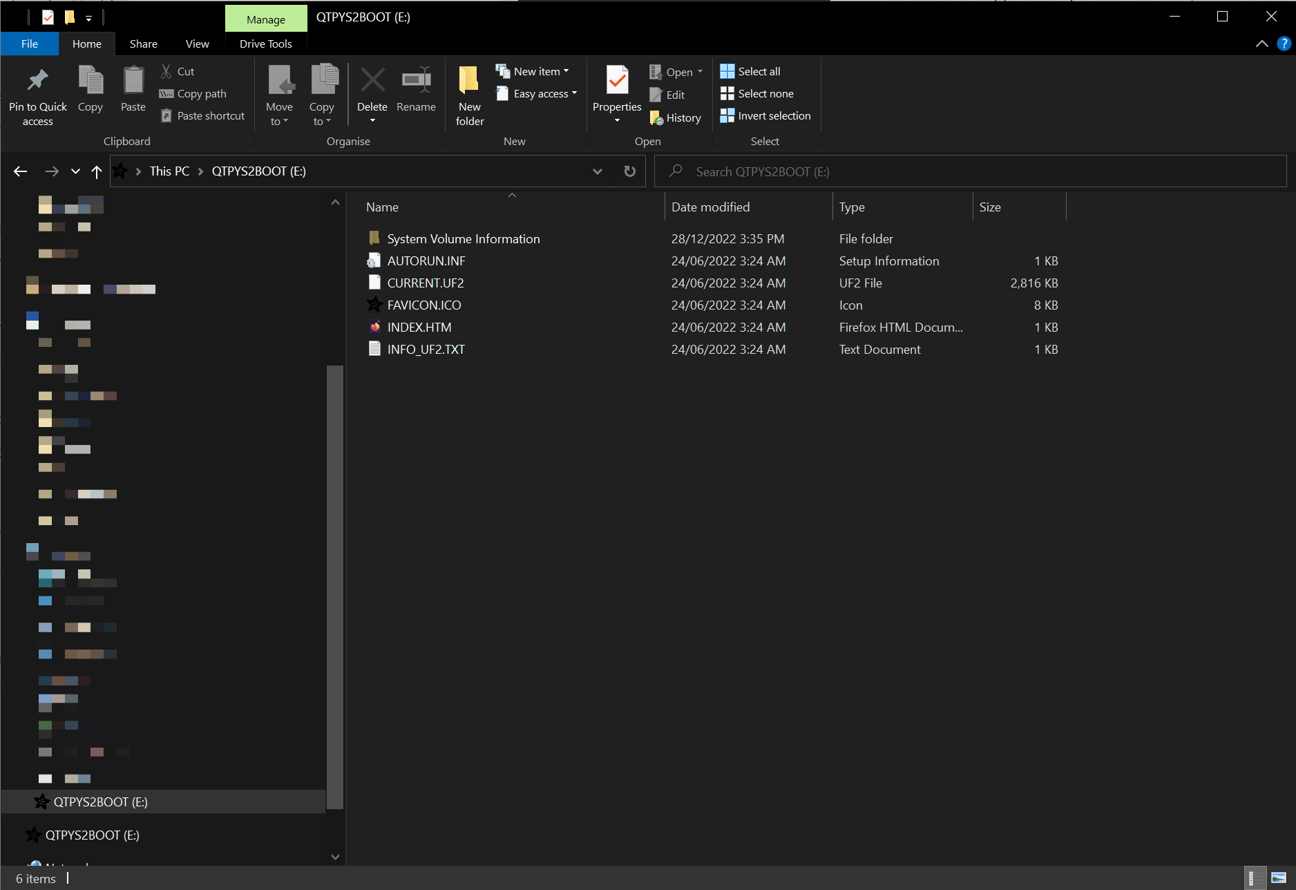
This will crate firmware.uf2 which we can then drag and drop into the new drive. The status LED will flash yellow whilst uploading (assuming the board has one and it's a NeoPixel LED) and the board will reboot into the app once finished. Or so the theory. For me, the board always went into the MSC mode, showing up as a USB drive. To understand why, I first had to learn about bootloaders and partitions.
Bootloaders and the partition table
Before our code be executed, the ESP goes through the following stages according to Application Startup Flow:
- First stage bootloader
- Second stage bootloader, and finally,
- Application startup
The first stage bootloader is hard coded into the microcontroller and can not be changed. From a user's perspective the most important thing this bootloader does is checking whether GPIO0 is pulled low and entering the download boot mode if so or alternatively, loading and running the second stage bootloader. The download boot mode is what allows us to flash the ESP for the first time or after bricking with some faulty code.
The second stage bootloader is code that has been flashed onto the ESP at an earlier stage. PlatformIO does it with every upload. This bootloader performs a number of tasks including choosing the partitions containing our application. This, amongst other things, enables OTA updates.
Let's now quickly look at the partition table we inherited from QT Py (with some formatting and correction of the comment at the top):
# ESP-IDF Partition Table
# Name,   Type, SubType,   Offset,  Size, Flags
# 2nd_bootloader,,,        0x1000,   28K,
# partition_table,,,       0x8000,    4K,

nvs,      data, nvs,       0x9000,   20K,
otadata,  data, ota,       0xe000,    8K,
ota_0,    app,  ota_0,    0x10000, 1408K,
ota_1,    app,  ota_1,   0x170000, 1408K,
uf2,      app,  factory, 0x2d0000,  256K,
ffat,     data, fat,     0x310000,  960K,
The details are explained in Partition Tables. For us it's sufficient to know that each row declares a partition with name, some type information, its start address in flash memory and its size. The first two (2nd_bootloader and partition_table) are enforced partitions and can't be controlled by the user (with some exceptions).
Remembering what we just learned about bootloaders, we see that the first stage bootloader is not present in the partition table as it is not part of the ESP's flash. The second stage bootloader must always be present. It will usually try to read otadata to find out which ota_N partition to load and execute it. If any of that fails, the bootloader will use the factory partition if present. The default bootloader is used, if we don't place a
bootloader-tinyuf2.bin file in the project's variants/ directory.
With that understanding, we can take another look at UF2.
UF2, take two
bootloader-tinyuf2.bin is a replacement of the second stage bootloader with added functionality to decide whether to start the user's app (usually in the
ota_0 partition) or to start the application that emulates a mass storage device. The code running the emulation is part of the tinyuf2.bin image in the
uf2 partition. Adafruit's documentation describes it as a third stage bootlaoder.
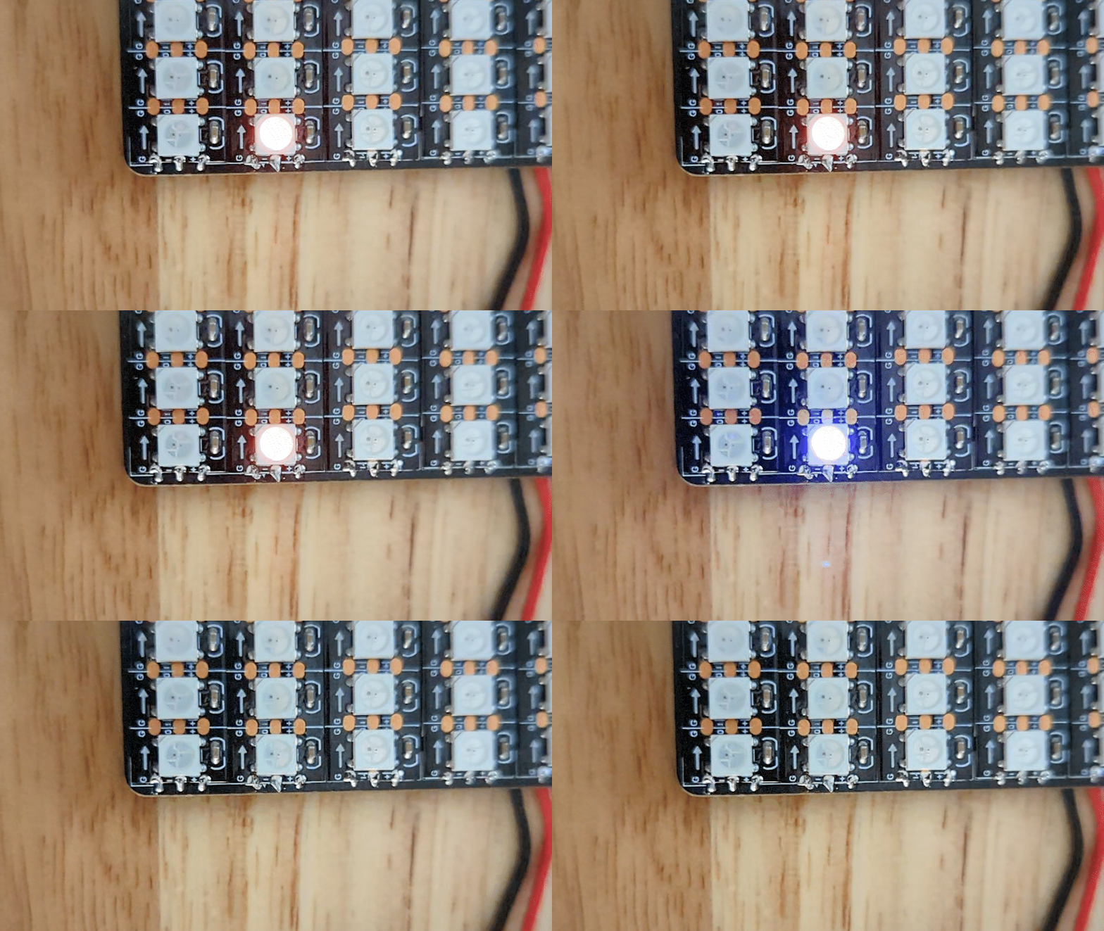
The second stage bootloader is where things seem to go wrong for me. My board happens to have a NeoPixel on the exact pin the QT Py board connects a status LED to so I can see status information from the UF2 bootloader. When booting up, the sequence I was seeing was off followed by red light and finally green light. But before that I saw a very brief purple light. I had to shoot a slow motion video to make sure that I'm not imagining things.

The intended operation of the UF2 bootloader is to show a purple indicator light, wait a couple of seconds for the user to press a button and, failing that, booting the user's application. Only if the user presses the button will we enter the mass storage device mode. So, it seems something is pressing that button. 🤔
The code implementing that behavior looks like below:
if ( boot_index != FACTORY_INDEX )
{
  board_led_on();

#ifdef PIN_DOUBLE_RESET_RC
  // Double reset detect if board implements 1-bit memory with RC components
  esp_rom_gpio_pad_select_gpio(PIN_DOUBLE_RESET_RC);
  PIN_INPUT_ENABLE(GPIO_PIN_MUX_REG[PIN_DOUBLE_RESET_RC]);
  if ( gpio_ll_get_level(&GPIO, PIN_DOUBLE_RESET_RC) == 1 )
  {
    ESP_LOGI(TAG, "Detect double reset using RC on GPIO %d to enter UF2 bootloader", PIN_DOUBLE_RESET_RC);
    boot_index = FACTORY_INDEX;
  }
#endif
}
So there must be a PIN_DOUBLE_RESET_RC configured somewhere. And indeed, we find it in the board.h of the tinyuf2 project:
// GPIO that implement 1-bit memory with RC components which hold the
// pin value long enough for double reset detection.
#define PIN_DOUBLE_RESET_RC   10
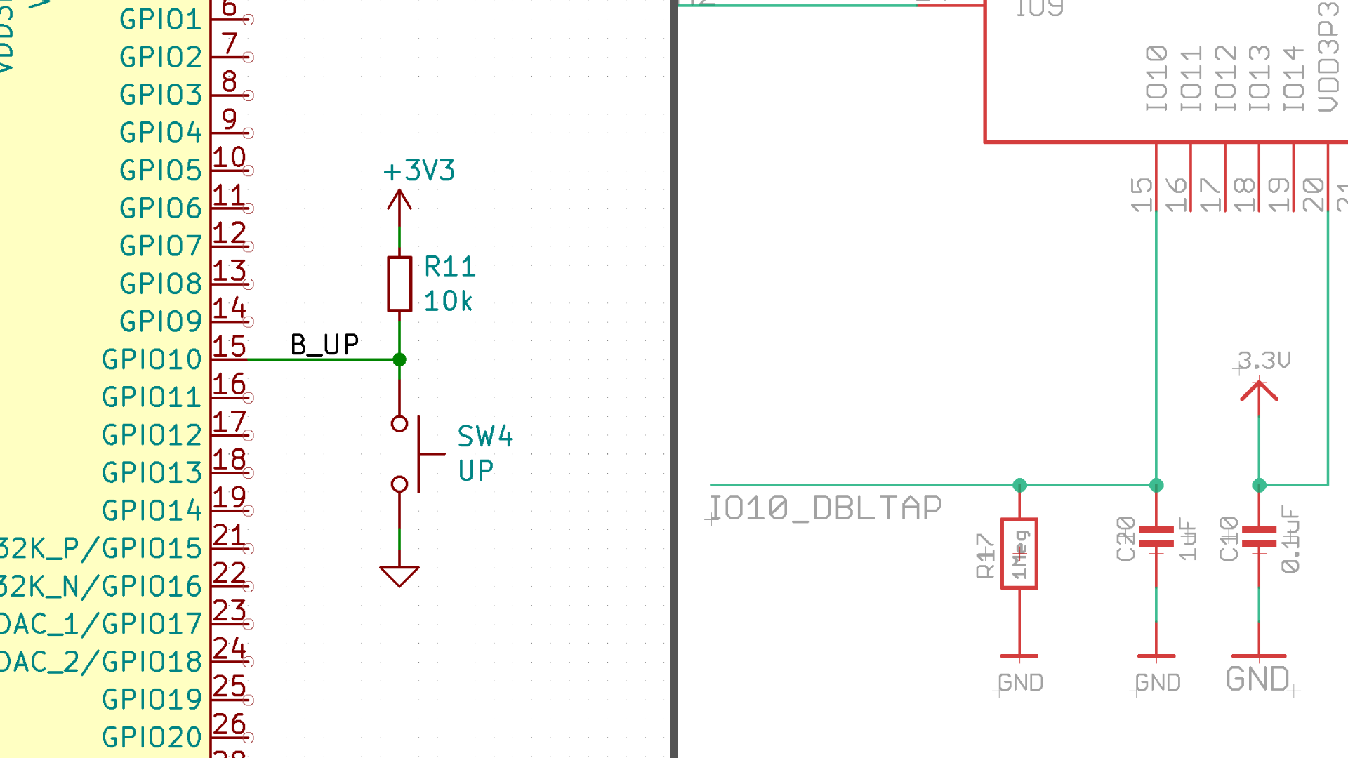
That's where it hit me: I probably have connected something to that pin. The original QT Py board uses some special circuitry to pull GPIO10 high when the user wants to enter the mass storage device mode. In my board however, there is a default high button connected to that pin explaining why we go into that mode every single time. 🎉

So all I have to do now is to press that button while booting the board. Easy.
For completeness, we can compile our own version of the UF2 bootloader. That would allow me to give it a better name, a nice fav icon and I could choose a different pin for the boot switching logic. For that we would need to check out the repo , create a new board under
ports/espressif/boards/ and run the following command:
make BOARD=neon allA better setup
UF2 is a way to enable a wide variety of boards to show up as mass storage device and use drag and drop to flash them with a new program. That is handy, especially in setups where ease of use is important like when teaching a class. For me, this is not what I need, so I won't continue using UF2 (now that I finally got it to work).
Instead, I use the following partition table, copied from the Arduino ESP project :
# ESP-IDF Partition Table
# Name,   Type, SubType,   Offset,  Size, Flags
# 2nd_bootloader,,,        0x1000,   28K,
# partition_table,,,       0x8000,    4K,

nvs,      data, nvs,       0x9000,  0x5000,
otadata,  data, ota,       0xe000,  0x2000,
app0,     app,  ota_0,     0x10000, 0x140000,
app1,     app,  ota_1,     0x150000,0x140000,
ffat,     data, fat,       0x290000,0x170000,
And I end up with a greatly reduced number of files in my project:
$project_root/
├── boards/
│   └── neon.json
├── src/
│   └── main.cpp
├── variants/
│   └── neon/
│       ├── partitions.csv
│       └── pins_arduino.h
└── platform.ini
The relevant section of the board config (neon.json) can be found below. I have omitted all sections that are not relevant for the working of the board.
{
  "build": {
    "filesystem": "fatfs",
    "arduino": {
      "ldscript": "esp32s2_out.ld"
    },
    "core": "esp32",
    "extra_flags": [
      "-DBOARD_HAS_PSRAM",
      "-DARDUINO_USB_CDC_ON_BOOT=1"
    ],
    "mcu": "esp32s2",
    "variant": "neon",
    "variants_dir": "variants"
  },
  "name": "Neon rev 1"
}
Note how I specify build.filesystem to be in line with the ffat partition. Without that, PlatformIO would use the default of spiffs.