

ESP32 PICO D4 pins
I love to build boards with bare ESP32-PICO-D4 chips. They are a little harder to use than the encased version but make for a nice looking board. It's just a tad more professional looking this way. Regardless of whether you use the bare chip or any of the encased versions, you will need to assign pins to a desired function. I wrote this is a little guide of how I go about doing that. If you find this sort of thing interesting, go check out the article about my quadrupedal robot.
UART and SPI
The GPIO matrix allows you to assign any function to almost any pin, however, some high speed functions like SPI and UART are slowed down by not using their respective standard pins. See 4.4.1 in technical reference manual.
Some high speed digital functions (Ethernet, SDIO, SPI, JTAG, UART) can bypass the GPIO Matrix for better high-frequency digital performance. In this case, the IO_MUX is used to connect these pads directly to the peripheral.
A list of functions available for a given pin are documented in 2.2 Pin Description of the data sheet. So far, SPI and UART are the features I have been dealing with. UART in particular is required for the USB communication and can't be mapped until we programmed the chip at least once, meaning we need to go with GPIO1 and 3 for that functionality.
Input only pins, ADC2 and SPI flash
The API Reference tells us that GPIO34-39 pins can only be used as input pins but are otherwise not limited in their functionality. I usually connect buttons or anything I need the ADC for. Which brings us to the fact that the ADC2 is not working if either WiFi or Bluetooth is in use. The affected pins can still read digital input though. Lastly, GPIO6, 7, 8, 11, 16 and 17 are used for the internal SPI flash and can't be used otherwise.
Strapping pins
The data sheet specifies a number of strapping pins in 2.3 Strapping Pins. Each of those pins is read when bootstrapping the chip and needs to be in a certain configuration in order to get the ESP32 working correctly. I found them a bit intimidating at first but they are actually quite simple:
- GPIO12 must not be pulled high for the chip to use 3.3V which is the usual configuration. Meaning we can easily use this pin for e.g. buttons that are normally pulled to GND.
- GPIO0 together with EN is usually used for the programmer and should not be used otherwise.
- GPIO2 must also not be pulled high for programming to work.
- GPIO15 should not be pulled low unless you don't care about debug logging while booting.
- GPIO5 should also not be pulled low.
Pin mapping in PlatformIO
You will need to create a board config and a pins_arduino.h if you created your own board, or want to change the pin function of an existing board. Assuming you created a board foo, you will need to create a file boards/foo.json. Use an existing board config as an example. In there you can now add a property build.variants_dir that points to a place holding your pins_arduino.h file. Again, make use of an existing file to simplify the process. I usually put the file under variants/${board_name}/.
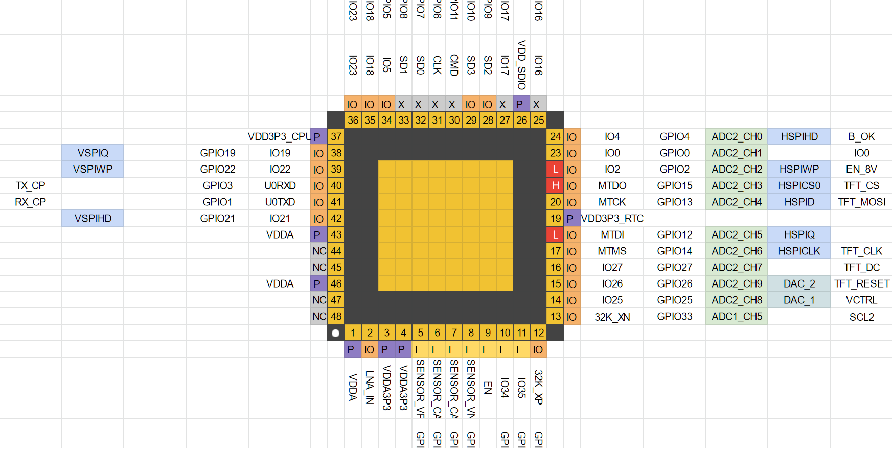
PCB layout
I use a crude spreadsheet to help me figure out where the various pins are physically located to help me assign them so that track routing is as easy as possible. Have a look.